ref: Hobby Boss # 84546 IDF Puma AEV

ref: Hobby Boss # 84546 IDF Puma AEV
The Puma (Poretz Michsholim Handasi) is an engineer combat vehicle based on the Shot tank (modified Centurion) and designed to breach obstacles. Entered in service in the early 1990s, it utilizes the hull of the Shot tank modified with an upgraded suspension on which is installed a heavily armored casemate accommodating up to 7 soldiers in addition to the driver.
The vehicle can be equipped with various demining systems: the Nochri rollers, a plow, a dozer blade at the front and the Carpet system at the rear. The Carper can launch up to 20 fuel air explosive rockets which detonate mines by overpressure. The rockets can be fired one by one or in a salvo. The rollers are then used to detonate the possible remaining mines. The Puma is also fitted with an electronic system to destroy remote-controlled charges. The Puma can also tow a mobile bridge to cross trenches.
The Puma is fitted with a remote weapon station (RWS) armed with a 7.62mm FN MAG MG and 3 more FN MAGs on a pintle mount. A 60mm mortar is mounted on the roof of the casemate between the both front hatches. On each side on the driver there are 6 smoke grenades dischargers which complement the defense means.
The protection of the Puma has been improved several times since its entry in service. The most recent vehicles are equipped with a RWS armed with a .50cal MG. A specialized version of the Namer should replace the Puma.
The kit
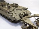
Released in 2019, it depicts an early version with the Nochri and the Carpet systems. The design of the model allows the modeler not to mount the both systems. The box contains 33 plastic sprues of which 4 are for the track links, 2 hull halves, 24 plastic tires, 1 clear parts sprue, 1 photoetched plate, 1 braided brass length, 1 chain length, 1 large decals sheet, 1 instructions booklet and 1 color plate for the decoration instructions. The total of parts is over 1200 of which around 200 are not used.
The level of detail is good, the carving is generally fine. The molding is good and the mold lines are easy to remove. The fit is generally good. However you have to thoroughly clean the parts especially those of the Carpet launcher. The PE parts are well designed and fit well. However the bending is sometimes difficult like for the headlights guards and the MG ammo boxes holders.
The antislip coating is omitted and needs to be added. Even if it is not planned, the rollers and the adapter to the hull can be removable with few modifications. The elevating jack of the Carpet is workable. Nonetheless it is advised to definitely glue it.
Hobby Boss provides a large decals sheet including marking for 7 different vehicles. Unfortunately the instructions sheet only presents one vehicle.
The build
It begins with the raodwheels assembly and gives the choice between two types. It is possible to mix the both types.
Then you need to assemble the suspension
in the steps 3 to 6. At the last step the swing arms of the idlers are not glued
to the hull but to the idlers. The sprockets, roadwheels and idlers are not
glued to facilitate the assembly and the painting of the tracks.
The back of part F18 needs to be thoroughly cleaned before being glued.
At step 7, you have to assemble the both
tracks. Those are made of 105 non workable individual links. You first have to
clean the 4 attachment points to the sprue. On my model I had to assemble 106
links for one track and 107 for the other.
When the tracks are set, they are painted and partly weathered like the whole
suspension. Then the tracks are installed.
Steps 8 to 13 are dedicated to the fenders. At step 8, you have to trim the back of the water cans so they can be inserted in their holders. The PE strap PE-A20 is modified because the buckle is hollow. The housings of the smoke grenades dischargers features prominent weld beams which must be thinned.
Step 14 deals with the RWS. The clear parts are masked with masking tape. The spotlight is not used. A dry test fit shows that the round hole in the casemate roof must be enlarged to fit the RWS.
Before going through steps 15 to 20 dealing with the details on the casemate and the upper part of the hull, I chose to glue these large parts onto the hull. However you need to first glue parts D19, D28, D29 and J6 to the casemate J22 (step 18) and the driver hatch onto the upper hull (step 21). To install the latter you need to glue the front part first.
At step 17, the 3 MG are assembled on their mount without the spotlights. The MG are set apart to avoid any damage.
At step 18, the antenna base D37 is replaced by a more realistic one from the spare parts box. An antenna is made of a length of 0.5mm styrene rod.
To build the stowage basket at step 18, I preferred to glue the sides J1 and J2 straight to the engine deck and then to glue the front and rear parts J19 and D1. The details and accessories can be glued beforehand.
On the drawing of step 21 the subassemblies FF and KK are already in place while they only come at step 22. To glue these subassemblies you need to cut the pins under the subassemblies.
The tow cables supports are glued to the vehicle side. To facilitate the installation of the locking pins, the part of the support against the hull is drilled out. At the rear the cables are retained by small chains attached to hooks which are provided as PE parts. The chains are made from thin electric wire which is twisted and crushed with pliers.
Step 23 deals with the side skirts. It is advised to enlarge the positioning holes at the back of supports C14. For more realism the rubber flaps are separated one from another.
From step 24 the assembly of the Nochri system begins. It is complete at step 28. The build is easy. However the cleaning of the parts needs to be seriously done because some mold lines are thick.
The rollers are assembled at step 24. When following the instructions the rollers are mobile as well as the chains attachments.
At steps 25 and 26 you have to assemble the push arms. To glue parts P13 you need to enlarge the positioning holes.
Step 27 is dedicated to the adapter. The parts require a thorough cleaning to allow a correct fit. Unlike what the instructions tell, I didn't glue the towing eyes D5 to the adapter but to the hull. Axis K13 secure the adapter without glue which allows the part to be removable. The eyes of the tensioning cables must not be glued to stay mobile.
To facilitate the painting the rollers are not attached to the adapter.
Steps 29 to 34 deals with the Carpet system. To get a perfect assembly you have to shorten all the fixing tabs of parts Q4, Q6, J3, M2 and M3. The assembly of the launcher and the munitions compartments is easier than it looks. To insert the munitions to the bottom of the compartments you must not glue parts Q8 in the compartments used.
Step 31 is dedicated to the assembly of the rockets. You have to glue the fins in a cross shape which is not easy. Each fin features a cut-out which must be enlarge to allow the insertion of the circle Q7. The rockets must not be inserted at step 32 because they need to be painted first.
At step 34, you assembled the side supports. At their front end there is a gap between the parts which is hidden by a little piece of plastic card. The end of the assembly is straightforward.
At this stage you should glue the rollers and the launcher to complete the build. To facilitate the painting they are painted separately then glued in place.
Before applying the paint it is possible to add the antislip coat using our own method
The decoration
With the IDF there is no surprise, you must use a Sinai Grey paint. I chose Ammo Mig 0131 reference. As mentioned above Hobby Boss provide at least 7 sets of markings but represents only one vehicle on the instructions plate.
For the weathering I started by applying a dark brown wash all over the vehicle. When it was dry, I applied oil dots mainly on the vertical surfaces. Then I melted them together with a brush soaked with thinner. I complemented these streaking with others made with water color pencils to have more color variations.
Mud splashes are realised with a mix of plaster, pigments and earth tone paint. This mixture is also used for the running gear. To complete the weathering some dust effects are created by spraying highly diluted light earth and sand paints.
The rockets are painted according the instructions. The markings provided are not used because they are invisible when the rockets are in their compartments.
Conclusion
This model measuring nearly 35 cm is impressive. Despite the huge number of parts, the assembly is easy. One can reproach that Hobby Boss did not feature the antislip coat and did not give instructions to use the various markings available on the decals sheet.
Despite this, this is a quality model, well designed, which deserves being recommended.
Click on a thumbnail to see the full sized picture

|

|

|

|

|

|

|

|

|

|

|
|

|

|

|

|

|

|
||
03/2024