réf: Hobby Boss 83834 French GCT 155mm AU-F1 SPH
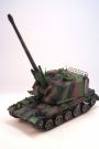
The Au-F1 self-propelled gun is the combination of the 155 mm high rate of fire gun (GCT) and an AMX 30 hull. The development started in 1972 and the first vehicles were built in 1977.
The turret can be fully traversed and the 39 caliber gun can be elevated from -4° to 66° and fire at a rate of 6 rounds per minute thanks to the autoloader. The 42 rounds are stored in the turret rear. The reloading takes 15 minutes for the crew of 4.
The firing range is 24 km and can be extended to 28 km with a RTC kit. Direct firing is possible with the dedicated sight.
For its self-protection, the Au-F1 is armed with a .50 cal MG. The vehicle is protected against NBC agents as well.
During its service life, 4 versions of the Au-F1 were developed in addition to the experimental version. The initial version (later renamed H) is fitted with an auxiliary power unit (APU made by Citroėn) on the right of the driver. The exhaust of the APU is flat. The vehicle is equipped with a single antenna right behind the vehicle commander.
The version T or CTI was fitted with an inertial navigation system which allowed the commander to permanently know his precise location, and a turbine which replaced the Citroėn APU. The new APU has a cover with a large bulge and a deflector on the right side. This detail enables to distinguish the T from the previous version.
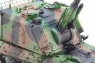
The version TM has only been built in 24 vehicles to test the new fire control system ATLAS. Externally, it is possible to spot this version by its three antenna bases (one in front of the commander kiosk for the automatic data link, one above the right loading door for the radio transmissions and the original base which is no longer used) and the plug for the Doppler radar located on the gun mantlet. This version was in service with a unique regiment.
The version TA is the current one. It keeps the TM turret but uses a AMX 30 B2 hull with the Mack E9 engine which obliged the rise of the turret by 12 cm. This version has no longer an APU, instead there are dedicated batteries.
The Au-F1 was deployed by the French army in Bosnia within the IFOR (operation Hermine) then in Kosovo in 1999 (operation Trident) and finally in Lebanon in 2006 (operation Daman). The Au-F1 was exported to Saudi Arabia and Iraq. It saw action during the Iraq-Iran war.
The kit
To begin with, the name of the kit is wrong. On the one hand GCT is the name of the gun and not of the vehicle, on the other hand the Au-F1 is a self-propelled gun so a SPG and not a howitzer (SPH).
Straight from the box, this kit cannot depict any existing version. Indeed, concerning the hull Hobby Boss mixed features from AMX 30 and AMX 30 B2 hulls. The turret is overall more accurate but the MG cradle is totally wrong and some details are ill-positioned or omitted as seen later.
The kit comprises 14 beige plastic sprues, 1 clear sprue, 2 hull halves, 1 turret shell, 2 photoetched parts frames, 1 decal sheet, 2 vinyl tracks and one length of brass cable. The instruction booklet is 20 pages and complemented by a color sheet for the decoration scheme.
The sprues are well protected and wrapped in plastic bags. Some fragile parts are protected by a foam film.
The level of detail is good and the molding is excellent. There are very few modling lines and nearly no ejection pin marks.
The build
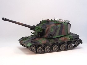
I decided to depict a Au-F1 TM.
The hull
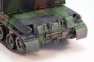
As soon as step 2, the first mistakes on the chassis need to be fixed. The stops B5 are typical of the 30 B2 chassis. They must be replaced by AMX 30 stops. In my case, I used Heller parts sent by a friend. The right light cluster A5 does not have the small black-out light on its top. You just need to remove it. Above the cluster, you need to drill a 1.5 mm diameter hole in the rear deck.
The most important part is to remove the 30 B2 details molded on the rear lower hull. These are the 2 round bosses with a large square screw inside and the large L-shaped boss.
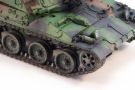
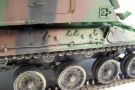
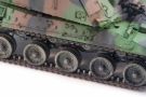
At step 3, the PE mass support PE-A9 is replaced by some plastic card as it is too large. The straps of the mass and those of the shovle must be redone and oriented downward. Hobby Boss has well designed the roadwheel arms which results in a perfect alignment.
At step 4, the idlers are not installed. There is a small gap in the positioning hole which will allow to install the tracks more easily.
The tracks tensioning screws A1 and A2 are a bit too long. You need to sand them so they sit flush with the hull.
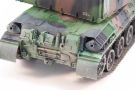
From step 6, you deal with the upper
hull. There again Hobby Boss made a lot of mistakes. You need to fill all the
positioning holes for the tools and the spare track links on the sides. New
brackets are made from plastic strips with the help of reference pictures. The
location of the tools are different from what Hobby Boss shows.
The driver mudguard PE-A2 is useless. A new one is made from plastic strip. The
vision blocks protections are replaced by plastic strip as well.
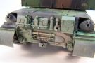
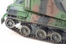
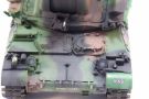
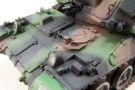
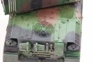
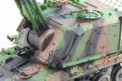
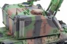
On the engine deck, you need to remove the third round cap in front of the ventilator (when looking frontward). The ventilator grille has 10 rings while there are 12 on the real part. It is impossible to fix this error. The PE protection grille is not used as it is a 30 B2 feature. Consequently, you need to engraved the 12 bolt heads locations around the grille and add the bolt heads. On the fenders E1 and E32, you just have to mark the separation between the different parts with a saw and to make a beveled cut right under the exhaust.
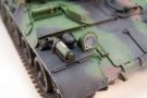
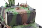
At step 9, the PE jerrycans brackets are shaped. The parts PE-B11 are shortened where is the hinge as they are too long. The jerrycans are too small compared to the brackets. They could be replaced. The decontamination bottle bracket is incomplete and the bottle is not issued. The whole is replaced by a resin part from the spare box.
At step 12, you must not install the "sight" PE-A11 on the right side. The ventilator grille PE-A1 is not used on this type of hull.
At step 13, you must not use parts E7
and E8 which are only for a 30 B2. Exhaust PE protections PE-B7 and PE-B8 must
be modified. The triangular part is contact with the hull is too large. You have
to shorten it or cut it away and make a new one in thin plastic card. For the
cables, Hobby Boss tells you to make two 85 mm lengths which is too long. 78 mm
are enough. You must add 2 cable brackets on each side. They are made from
thick plastic card which is shaped with a thin file.
The fire extinguishers heads are hollowed. The one on the right fender must be
oriented outward.
At step 14, the headlight guards must be sanded to help fit the glasses. Do not forget to paint the inside before installing the protections. The latches B3 for the batteries plates are not right for a Au-F1. The real ones are welded to the hull sides and look like large wingnuts. They are made with plastic rod.
The 2 hull halves can be glued together. The tools are installed at the right location. The tracks will be fitted after the painting. They must be glued with CA glue.
The turret
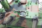
As soon as step 16, Hobby Boss gives unclear instructions. The way part G27 is glued onto G48 is mysterious. You must look at the following steps drawings to understand how to do. Moreover, Hobby Boss mentions that removing the radar cable plus is an option. If the plug is removed, so you only need one antenna base and must remove the molded details of the other bases.
Ammunition racks are simplified for those who want to show the loading doors open.
At step 19, the axes of the travel lock G39 are too large and must be sanded.
At step 20, the cover of the sight G4 must be sanded so it sits in its place.
At step 21, the muzzle brake requires some work to eliminate the glue seam and fill two holes.
At step 22, Hobby Boss proposes to
detail the inner faces of the doors which is useless as there is no interior to
show. The antenna bases are installed according to the step 16 choice. If the
radar cable plus has been removed, the base G10 is glued next to the part G50
and not where it is mentioned by Hobby Boss. In this case, the locating lug is
removed.
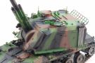
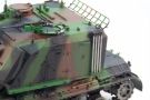
The searchlight is modified to be in the lower position as often seen on the
pictures. Handles H11 on the loading doors must be placed at an angle and
downward.
At step 23, the commander kiosk interior can be detailed with clear vision blocks. Unless you put the hatch open, it is useless.
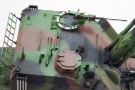
To finish the turret, you must install the antenna base G25 and add an antenna if the radar cable plus has been kept. You also need to add the lock for the radio operator hatch which has been omitted by Hobby Boss as well as the MG travel lock. The commander hatch lock must be moved rearward and closer to the hatch. You also must make a new MG cradle as the one issued is totally wrong. Step 24 is pure fantasy.
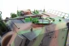
The decoration
Having chosen to depict a Au-F1 TM, the
decoration will necessarily represent a gun of the 40th artillery regiment. The
camouflage scheme is not totally accurate. One can refer to the official one
which is available in this site
France 1/35.
However, when looking at pictures, one can notice that the scheme is rarely
applied by the rule.
For the French camo shades, I mixed different Tamiya references. The green is a mix of XF-5 Flat Green and X-24 Park Green. The brown is a mix of XF-10 Flat Brown, XF-52 Flat Earth and a bit of XF-3 Flat Yellow. The black is XF-1 Flat Black.
Once the camo has been applied, I set the decals. Hobby Boss gives the decals for a single gun from the correct unit but they need to be modified as they depict more recent markings (Au-F1 TA). The modification is just painting black the battery number B1 and is replace it by a number from the Echelon sheet for the Leclerc.
The weathering started with the oil dots technique to break the monotony of the shades. Then some pigments were mixed with mat varnish and sprayed to the lower hull to create a dry mud effect. The dust is represented with successive light coats of XF-57 Buff. To finish, streaking are added with various oil shades.
Conclusion
This kit is not recommended because of the excessive number of mistakes and omission by Hobby Boss. It is a shame as it builds well and the fit is good. Meng model is not perfect but much more accurate. It just misses the connector type tracks which are in the Hobby Boss box. The choice is up to you.
|
|

|

|
|
|
|
|

|
|
|
|
|
|
|
|
|
|
|
|
|
|
|
|
|
|
|
|
|
|

|
||||